This is an old revision of the document!
WAN Failover
WAN Failover allows AstLinux to detect if your primary WAN link goes down and switch traffic to an alternate secondary WAN link.
While the concept is quite simple, and detecting a failed WAN link is straightforward, keeping all your services (including Asterisk) happy with the switchover can be tricky. Supported is an optional action script that is called to allow you to restart any services or make network adjustments following a failover or a failback.
Note: AstLinux 1.2.1 or later is required
External Failover Interface
The most common situation is to use a separate, secondary external interface (Failover Interface) to connect to your backup WAN link. Start by specifying that interface…
Select the Network Tab in the web interface.


Continue the configuration by clicking on the WAN Failover Configuration button.
Note -> As a special case, a Failover Interface does not need to be defined if a “Secondary Gateway” is manually defined in the “WAN Failover Configuration”.
WAN Failover Configuration

The above Target IPv4 Host IP's is an example that should work in general, but you are encouraged to find a unique set for your installation. ICMP (ping) is used to query the WAN link host's status. It is recommended to have at least 2 hosts defined, since a failover is triggered only when all the Target IPv4 Hosts are unreachable.
Note -> All the Target IPv4 Hosts addresses are tied (static route) via the primary interface, so do not choose any Target IPv4 addresses that you also want to access during failover.

The above options should be self-explanatory. The Primary/Secondary Delay is a period of time that no switch can occur, hysteresis, to prevent too frequent WAN link changes.

If you wish to be notified of Failover/Failback WAN link changes via email, specify a “Notify Email Addresses To:” (space separate multiple email addresses). Of course the “Outbound SMTP Mail Relay:” section of the Network tab must be valid for this to work.

Typically the “Secondary Gateway” fields should be left empty. Defining a “Secondary Gateway” will automatically find the associated interface, used when the Failover Interface is not defined in the Network tab.
Tip -> The “Secondary Gateway” must be a valid IP address contained in a subnet of previously defined interfaces in the Network tab (e.g. a second router with a separate internet connection reachable over your LAN).
Failover Interface Settings
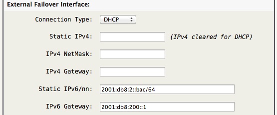
The above network options define the “External Failover Interface” settings, just as the primary external interface is defined in the Network tab.
Note -> Any changes to these External Failover Interface settings will require a system reboot to be applied.
Failover Destination Routes

If you have a full time backup secondary WAN link you may find it wasteful having it not carrying any data most of the time. As a feature you many define a space separated list of destination IP's or CIDR's that will be routed over the Failover WAN link all the time.
Another useful case is when the Failover WAN link contains a network device with a HTTP configuration at a specific IP address, that IP address can be added so it will be routed via the Failover WAN link.
Action Script (optional)
Some network services don't like the network path changing, as such you can define an executable shell script to quickly act on WAN link changes.
The script must be found at /mnt/kd/wan-failover.script and be made executable…
chmod 755 /mnt/kd/wan-failover.script
Example: /mnt/kd/wan-failover.script
#!/bin/sh

##
## wan-failover action script
##
## Automatically called after any WAN link change
##
state="$1"
primary_if="$2"
primary_gw="$3"
secondary_if="$4"
secondary_gw="$5"
secondary_gw_ipv6="$6"

case $state in

SECONDARY)
  ## Switched to Failover using secondary WAN link
  ;;

PRIMARY)
  ## Switched back to normal using primary WAN link
  ;;

esac

exit 0
Action Exit Script (optional)
Note: AstLinux 1.3.7 or later is required
Conditionally test when a Secondary → Primary WAN link change is allowed to occur, by executing a script.
If this script has an exit value of 0 the link change occurs, else with any other exit value the failover remains on the Secondary WAN.
The script must be found at /mnt/kd/wan-failover-exit.script and be made executable…
chmod 755 /mnt/kd/wan-failover-exit.script
Example: /mnt/kd/wan-failover-exit.script
#!/bin/sh

##
## wan-failover-exit action script
##
## Automatically called before any Secondary -> Primary WAN link change
## and the Primary WAN link is reachable.
##
## If this script has an exit value of 0 the link change occurs.
## Else with any other exit value, the failover remains on the Secondary WAN.
##
## Note: Do not 'sleep' in this script, exit promptly.
##
state="$1"
primary_if="$2"
primary_gw="$3"
secondary_if="$4"
secondary_gw="$5"
secondary_gw_ipv6="$6"

## Sanity check, 'state' must be set properly
if [ "$state" != "SECONDARY_EXIT" ]; then
  exit 0
fi

. /etc/rc.conf

##
## Allow Secondary -> Primary WAN link change ?
##

## Custom user.conf variable, if "yes" failover will not return to the Primary WAN link
if [ "$CUSTOM_WAN_FAILOVER_STICKY" = "yes" ]; then
  exit 1
fi

## Check Asterisk active calls, remain on the Secondary WAN link until no active calls
active_calls="$(asterisk -rx 'core show channels' | sed -n -r -e 's/^([0-9]+) +active +call.*$/\1/p')"
if [ -n "$active_calls" ] && [ $active_calls -gt 0 ]; then
  exit 1
fi

exit 0
Testing Failover
Before any WAN Failover configuration can be put into production it must be thoroughly tested. One useful tool is the command…
service failover test
Resulting in “Testing WAN Failover…” This command forces a failover in software without disrupting the primary WAN link.
When your testing is complete, you can either wait for the automatic return to the primary WAN link, or speed up the process with…
service failover restart
Of course manually disrupting the primary WAN link to force a failover should also be included in your testing.
PPPoE on Failover Interface
AstLinux supports at most one instance of PPPoE internally, and when configured, it is always the Default Route destination. If you need PPPoE for the failover external interface, your only options are to perform the PPPoE encapsulation on another device.
This can be achieved in two ways:
- Terminating the WAN connection with a PPPoE capable router. In this scenario both Astlinux and the router will perform NAT which can be problematic for some traffic types such as voice. If voice traffic is being tunnelled through a VPN however, this should not be an issue.
- Terminating the WAN connection with a PPPoE capable modem configured into half bridge mode. In this scenario, the modem authenticates via PPPoE but bridges the Public IP Address to the Astlinux failover external interface via DHCP. This may be a better solution as an extra NAT is not added to the network path.
Note -> If you are using half bridge mode, unless you have a static IP Address from your ISP the modem will not update the IP when it is changed until the next dhcp renewal. Due to this, most half-bridge modems use extremely short dhcp lease times which is not optimal. It is better to avoid dynamic IP's altogether and set the Astlinux failover external interface statically to the Public IP, with the DHCP client disabled in the modem.
Example: 4G/LTE Modem Failover
For an always-up backup solution using 4G/LTE, the Netgear LB1120 (LB1121 PoE support) 4G/LTE Modem may be a solution.
Tip -> Be sure to upgrade the LB1120/1121 to the latest firmware before enabling “Bridge Mode”, if desired.
The Netgear LB1120, LB1121 was released at the end of 2017, and tested to work with AstLinux. Similar products may also be available, referred herein as “4G/LTE Modem”.
Most 4G/LTE providers only support outbound-only (NAT'ed), IPv4-only, dynamic IPv4 address network transport, any basic failover configuration over 4G/LTE must deal with those constraints. If this basic network transport works for you then simply connect the 4G/LTE Modem to your failover interface, enable “Bridge Mode” in the 4G/LTE Modem and in the AstLinux “Network tab → WAN Failover Configuration” set …
External Failover Interface:
  Connection Type: [DHCP]

External Failover Destination Routes:
  192.168.5.0/24
The added 192.168.5.0/24 route is to allow access to the web interface of the 4G/LTE Modem when in Bridge Mode.
Alternatively, if an extra layer of NAT is not an issue (ex. with only a WireGuard VPN over it), the 4G/LTE Modem can use the default Router Mode. You may minimize services by disabling the “DHCP Server” and “VPN Passthrough”.
Netgear → Advanced tab …
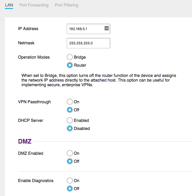
AstLinux “Network tab → WAN Failover Configuration” …
External Failover Interface:
  Connection Type: [Static IP]
      Static IPv4: 192.168.5.5
     IPv4 NetMask: 255.255.255.0
     IPv4 Gateway: 192.168.5.1

External Failover Destination Routes:
  (empty)
When in Router Mode, no added route is needed for access to the web interface of the 4G/LTE Modem.
But, there is another way …
Enhanced WAN Failover using WireGuard:
If you are able to run a second AstLinux instance on a static IPv4 address you can establish an always-up WireGuard VPN over the 4G/LTE connection. When idle the VPN typically consumes 0.5 MB/day of data.
One such solution providing an AstLinux instance in the cloud: Linode KVM, Hosted Guest VM
With this setup, both IPv4 and IPv6 can be supported as well as allowing inbound traffic to the failover. When failover occurs, all the IPv4/IPv6 traffic is sent over the WireGuard VPN to the “Static” WireGuard endpoint. In addition the failover transport is encrypted.
To be clear, while the WireGuard VPN is established over IPv4-only, the tunnel can simultaneously transport IPv4 and IPv6.
Example AstLinux “4G/LTE”: Cable/DSL Modem on external interface and 4G/LTE Modem on failover interface.
Internal 1st LAN IPv4: 192.168.101.1/255.255.255.0
Internal 1st LAN IPv6: fda6:a6:a6:d1::1/64
WireGuard IPv4: 10.4.1.1/255.255.255.0
WireGuard IPv6: fda6:a6:a6:ff::1/64
IPv6 ULA/NPTv6: fda6:a6:a6::/56
Example AstLinux “Static”: Static IPv4 (or IPv4/IPv6) on external interface.
Routable Public IPv4: 1.2.3.4
WireGuard IPv4: 10.4.1.100/255.255.255.0
WireGuard IPv6: fda6:a6:a6:ff::100/64
IPv6 ULA/NPTv6: fda6:a6:a6::/56
AstLinux “4G/LTE” Endpoint Configuration
Network tab → WireGuard Configuration:
Tunnel Options:
  IPv4 Address: 10.4.1.1
  IPv4 NetMask: 255.255.255.0
  IPv6/nn Address: fda6:a6:a6:ff::1/64
/mnt/kd/wireguard/peer/wg0.peer snippet
[Peer]
PublicKey = <For Static Endpoint>
Endpoint = 1.2.3.4:51820
AllowedIPs = 0.0.0.0/0, ::/0
PersistentKeepalive = 25
Network tab → WAN Failover Configuration:
WAN Failover:
  Failover: [enabled]
  Secondary Gateway IPv4: 10.4.1.100
  Secondary Gateway IPv6: fda6:a6:a6:ff::100

External Failover Interface:
  Connection Type: [Static IP]
      Static IPv4: 192.168.5.5
     IPv4 NetMask: 255.255.255.0
     IPv4 Gateway: 192.168.5.1

External Failover Destination Routes:
  IPv4 Routes: 1.2.3.4
Network tab → Firewall Configuration:
Firewall Options:
  _x_ Allow WireGuard VPN tunnel to the [1st] LAN Interface(s)
AstLinux “Static” Endpoint Configuration
Network tab → WireGuard Configuration:
Tunnel Options:
  IPv4 Address: 10.4.1.100
  IPv4 NetMask: 255.255.255.0
  IPv6/nn Address: fda6:a6:a6:ff::100/64
/mnt/kd/wireguard/peer/wg0.peer snippet
[Peer]
PublicKey = <For 4G/LTE Endpoint>
AllowedIPs = 10.4.1.1/32, 192.168.101.0/24, fda6:a6:a6:ff::1/128, fda6:a6:a6:d1::/64
/mnt/kd/rc.conf.d/user.conf snippet
NAT_FOREIGN_NETWORK="192.168.101.0/24"
Note that one AstLinux “Static” server can support many remote failover AstLinux “4G/LTE” boxes provided all are unique LAN subnets.
Example: WiFi Bridge Failover
For those cases where a failover network is seldom required, a WWAN source such as LTE is often available via a WiFi hotspot device or enabling a personal hotspot using an Android or iOS device via WiFi. In this case providing a pre-configured WiFi client connected to the failover external interface can provide a very cost-effective failover solution.
Unfortunately WWAN hotspot solutions typically add a level of NAT to the network path, so it is important the WiFi client is configured as a “bridge” so as to not add yet another level of NAT.
In this example an Apple iOS device with LTE Personal Hotspot enabled will be the WWAN source. This example's WiFi client will be a Ubiquiti PicoStation M2 (PICOM2HP), alternatively a Ubiquiti NanoStation locoM2 (LOCOM2) should also work well, but has a 60 deg. directional antenna instead of the omni-directional antenna of the PicoStation.
The Ubiquiti airOS defaults to “bridge” mode so no additional NAT'ing is created.
Ever since iOS 4.3, the Personal Hotspot subnet is 172.20.10.1/28 with a DHCP server offering 172.20.10.2 through 172.20.10.14. But, since the gateway address 172.20.10.1 (and DHCP server) will come and go, ignore the DHCP server and manually address all the hosts since you have control who has access to the subnet.
In the Network tab assign an unused interface to the External Failover Interface and manually address 172.20.10.14/28 with a gateway of 172.20.10.1 as follows:
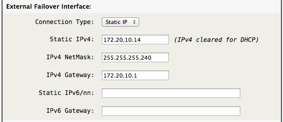
Next define the WiFi client bridge as 172.20.10.13 with a gateway of 172.20.10.14 so it talks back to AstLinux not via the iOS device:
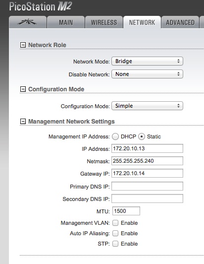
Finally, enable the iOS Personal Hotspot and then configure the WiFi client bridge (“Station” mode in Ubiquiti lingo) to lock in to only the iOS device:
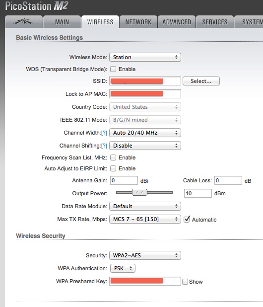
Tip -> In this example the Output Power is reduced since the iOS device is usually very close to the WiFi client.
That's it, you will probably want to create a /mnt/kd/wan-failover.script executable script to handle reloading selected services or Asterisk during each switchover, and in this special case where the secondary gateway may not always be connected, you may want to test for the secondary_gw before acting, such as:
if fping -q -t 100 "$secondary_gw"; then
  ... do stuff ...
fi